

单击打开
平顶无热 AWG/ Flat Top Athermal AWG
Optical signal transmission diagram
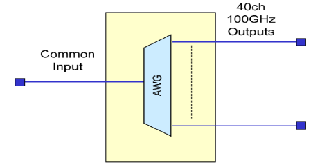
Figure 1 Optical signal transmission characteristics
Channels List:Passbands for 40 channel AAWG
|
Channel |
On ITU grid in C-band Even |
On ITU grid in C-band ODD |
||
|
Frequency(THz) |
Wavelength(nm) |
Frequency(THz) |
Wavelength(nm) |
|
|
1 |
196 |
1529.553 |
196.05 |
1529.163 |
|
2 |
195.9 |
1530.334 |
195.95 |
1529.944 |
|
3 |
195.8 |
1531.116 |
195.85 |
1530.725 |
|
4 |
195.7 |
1531.898 |
195.75 |
1531.507 |
|
5 |
195.6 |
1532.681 |
195.65 |
1532.290 |
|
6 |
195.5 |
1533.465 |
195.55 |
1533.073 |
|
7 |
195.4 |
1534.250 |
195.45 |
1533.858 |
|
8 |
195.3 |
1535.036 |
195.35 |
1534.643 |
|
9 |
195.2 |
1535.822 |
195.25 |
1535.429 |
|
10 |
195.1 |
1536.609 |
195.15 |
1536.216 |
|
11 |
195 |
1537.397 |
195.05 |
1537.003 |
|
12 |
194.9 |
1538.186 |
194.95 |
1537.792 |
|
13 |
194.8 |
1538.976 |
194.85 |
1538.581 |
|
14 |
194.7 |
1539.766 |
194.75 |
1539.371 |
|
15 |
194.6 |
1540.557 |
194.65 |
1540.162 |
|
16 |
194.5 |
1541.349 |
194.55 |
1540.953 |
|
17 |
194.4 |
1542.142 |
194.45 |
1541.746 |
|
18 |
194.3 |
1542.936 |
194.35 |
1542.539 |
|
19 |
194.2 |
1543.730 |
194.25 |
1543.333 |
|
20 |
194.1 |
1544.526 |
194.15 |
1544.128 |
|
21 |
194 |
1545.322 |
194.05 |
1544.924 |
|
22 |
193.9 |
1546.119 |
193.95 |
1545.720 |
|
23 |
193.8 |
1546.917 |
193.85 |
1546.518 |
|
24 |
193.7 |
1547.715 |
193.75 |
1547.316 |
|
25 |
193.6 |
1548.515 |
193.65 |
1548.115 |
|
26 |
193.5 |
1549.315 |
193.55 |
1548.915 |
|
27 |
193.4 |
1550.116 |
193.45 |
1549.715 |
|
28 |
193.3 |
1550.918 |
193.35 |
1550.517 |
|
29 |
193.2 |
1551.721 |
193.25 |
1551.319 |
|
30 |
193.1 |
1552.524 |
193.15 |
1552.122 |
|
31 |
193 |
1553.329 |
193.05 |
1552.926 |
|
32 |
192.9 |
1554.134 |
192.95 |
1553.731 |
|
33 |
192.8 |
1554.940 |
192.85 |
1554.537 |
|
34 |
192.7 |
1555.747 |
192.75 |
1555.343 |
|
35 |
192.6 |
1556.555 |
192.65 |
1556.151 |
|
36 |
192.5 |
1557.363 |
192.55 |
1556.959 |
|
37 |
192.4 |
1558.173 |
192.45 |
1557.768 |
|
38 |
192.3 |
1558.983 |
192.35 |
1558.578 |
|
39 |
192.2 |
1559.794 |
192.25 |
1559.389 |
|
40 |
192.1 |
1560.606 |
192.15 |
1560.200 |
Fiber Type:
SMF-28 900um compliant.
Environmental Conditions
|
Parameters |
Notes |
Specifications |
Units |
||
|
Min |
Typ |
Max |
|||
|
Operating Temperature |
|
-5 |
|
+65 |
°C |
|
Storage Temperature |
|
-40 |
|
+85 |
°C |
|
Relative Humidity |
|
0 |
|
90 |
% |
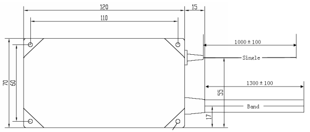
Mechanical Dimensions
120 mm x 70 mm x 10 mm
The screw space is 110*60 mm.
Ordering Information: HC-AWG- A-B-C-D-E-F-G
|
A |
B |
C |
D |
E |
F |
G |
|
工作波段 |
通道数 |
通道间隔 |
起始通道 |
芯片类型 |
尾纤长度 |
连接头 |
|
C: C-Band |
16: 16CH |
100: 100GHz |
C60: C60 |
FA: 平坦无热 |
05: 0.5m |
00: None |
|
X: 客户指定 |
24: 24CH |
200: 200GHz |
H59: H59 |
GA: 高斯无热 |
10: 1.0m |
FP: FC/UPC |
|
|
32: 32CH |
050: 50GHz |
C59: C59 |
X: 客户指定 |
15: 1.5m |
FA: FC/APC |
|
|
40: 40CH |
X: 客户指定 |
H58: H58 |
|
X: 客户指定 |
SP: SC/UPC |
|
|
44: 44CH |
|
X: 客户指定 |
|
|
SA: SC/APC |
|
|
48: 48CH |
|
|
|
|
LP: LC/UPC |
|
|
X: 客户指定 |
|
|
|
|
LA: LC/APC |
|
|
|
|
|
|
|
X: 客户指定 |
Optical Specifications
|
Parameters |
Notes |
Specifications |
Units |
|
|
Min |
Max |
|||
|
Channels |
|
40 |
Ch |
|
|
Channel Spacing |
|
100 |
GHz |
|
|
Reference Pass-band |
Relative to ITU Grid |
± 0.1 |
nm |
|
|
ITU Frequency |
On ITU grid in C-band Even |
196.00 |
192.10 |
THz |
|
ITU Wavelength |
On ITU grid in C-band Even |
1529.553 |
1560.606 |
nm |
|
ITU Frequency |
On ITU grid in C-band ODD |
196.05 |
192.15 |
THz |
|
ITU Wavelength |
On ITU grid in C-band ODD |
1529.163 |
1560.200 |
nm |
|
Center Frequency Accuracy |
Maximum of the absolute deviation of the 3 dB center wavelength from ITU grid over all channels |
-0.05 |
+0.05 |
nm |
|
Insertion Loss |
Maximum of the insertion loss across the ITU pass-band over all channels |
|
5.5 |
dB |
|
Insertion Loss Uniformity |
Maximum insertion loss variance across all channels |
|
1.3 |
dB |
|
Ripple |
Maximum of the loss variance across the ITU pass-band over all channels |
|
0.5 |
dB |
|
0.5 dB Bandwidth |
0.5 dB from min Insertion Loss, full width, worst case polarization |
0.2 |
|
nm |
|
1dB Bandwidth |
1dB from min Insertion Loss, full width, average polarization |
0.4 |
|
nm |
|
3dB Bandwidth |
3 dB from min Insertion Loss, full width, average polarization |
0.55 |
|
nm |
|
20 dB bandwidth |
20 dB from min Insertion Loss, full width, average polarization |
|
1.2 |
nm |
|
Adjacent Channel Isolation |
Ratio of peak transmission to the maximum transmission over both adjacent pass-bands |
25 |
|
dB |
|
Non-Adjacent Channel Isolation |
Ratio of peak transmission in channel pass-bands to maximum transmission over all non-adjacent pass-bands |
30 |
|
dB |
|
Total Crosstalk |
Ratio of power in channel to power in all other pass-bands |
21 |
|
dB |
|
Polarization Dependent Loss |
Maximum ratio of transmissions over all polarization states, over the ITU pass-band |
|
0.5 |
dB |
|
Return Loss |
|
40 |
|
dB |
|
Polarization Mode Delay (PMD) |
In Reference Passband over all channels |
|
0.5 |
ps |
|
Chromatic Dispersion |
In Reference Passband over all channels |
-15 |
15 |
ps/nm |
