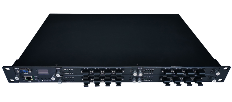
Оборудование оптического байпаса MPO
MPO bypass switch system is a kind of light is applied to optical fiber communication field and can automatic bypass fault intelligent network node system, through the automatic identification of the network node power supply system and optical signal output state, when the node fault system, automatically instantaneous switch, light path around the fault of network nodes, so as to avoid network node all resistance barriers, maintain system connected to normal。
Features
Transparent transmission for optical physical links
Supports gigabit and gigabit network
Multiple heartbeat patterns
Low insertion loss, high stability instantaneous switch
Range of application
Network security node device protection system
Remote transfer device node protection system
Technical parameters
|
parameter |
Unit |
Indicators |
|
|
Single mode |
Multimode |
||
|
Test the wavelength |
nm |
1310 / 1550 |
850 |
|
Insertion loss |
dB |
≤ 1.5 |
≤ 1.5 |
|
Return loss |
dB |
≥ 45 |
≥30 |
|
Crosstalk |
dB |
≥ 55 |
≥ 35 |
|
Wavelength dependent loss |
dB |
≤ 0.25 |
≤ 0.25 |
|
Polarization dependent loss |
dB |
≤ 0.1 |
≤ 0.1 |
|
Switch time |
ms |
< 10 |
< 10 |
|
Optical fiber type |
SM(9/125um) |
MM(OM3) |
|
|
Optical connector |
MPO/PC(Male head) |
||
|
Monitor the port |
RJ45、RS-232 |
||
|
Working power supply |
V |
AC: 85 ~ 264(50/60Hz)or DC: 36 ~ 72 |
|
|
Power consumption |
W |
< 5 |
|
|
Working temperature |
℃ |
-5 ~ 55 |
|
|
Storage temperature |
℃ |
-20 ~ 75 |
|
|
The case type |
1U standard 19 "rack(483×220×44mm) |
||
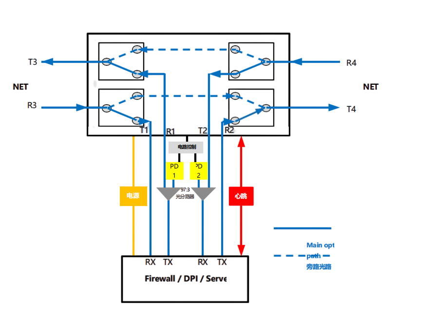
The Optical path principle

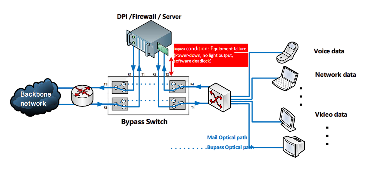
Application solutions

Networking application of intelligent light Bypass switch
Order information:HC-OBP-A-B-C-D-E-F-G
|
A |
B |
C |
D |
E |
F |
G |
|
Structure |
Working wavelength |
Protect the way |
To protect the imlet |
Number of light detection paths |
Heartbeat/communication interface |
Power supply mode |
|
1:1U Stationary |
3: 13/15 single mode |
1: useing |
1: 1 disc 4 road |
0: No ground light |
1:USB |
1: USB power supply |
|
2: 1U Insert disc |
4: More than 85 die |
3: Power loss + passive heartbeat |
2: 2 plate 8 road |
1: R1 R2 detection |
2:RS232 |
2:AC85~265V |
|
X: Other |
X: Other |
4: Power loss + active heartbeat |
3: 3 plate of no.12 |
2: R1 and R4 detection |
3:RJ45 |
3:DC36~72V |
|
5: Detecting light + passive heartbeat |
4: Four set 16 road |
X: Other |
4:RS232/RJ45 |
4: Double AC |
||
|
6: Light detection + active heartbeat |
X: Other |
5:RS485 |
5: Double DC |
|||
|
X: Other |
6:RS485/RJ45 |
6: Hybrid AC/DC |
If you need more information , Please contact us.
