

Click to open expanded view
10G SFP+ Passive Direct Attach Copper Cable
Product Features
Ø Support for multi-gigabit data rates up to 10.3125Gbps
Ø Wire AWG: AWG30, AWG24
Ø Low power consumption < 0.5W
Ø Power supply :+3.3V
Ø RoHS 2.0 complaint
Ø Small diameter cable design
Ø Compatible to SFP+ MSA
Ø Available length (in meters): 1, 2, 3... 7
Ø Electrical interface compliant to SFF-8431
Ø Cable type: Passive Copper Twinax Cable
Ø Commercial temperature range (COM): 0~ 70 °C•
Ø Improved Pluggable Form Factor (IPF) compliant for enhancedEMI/EMC performance
Applications
Ø 10G BASE Ethernet
Ø Switches / Routers
Ø Home small network
Description
The SFP+ passive cable assemblies are high performance, cost effective I/O solutions for 10G Ethernet and 10GFiber Channelapplications. SFP+ copper modules allow hardware manufactures to achieve high port density, configurability and utilizationataverylow cast and reduced power budget. The high speed cable assemblies meet and exceed Gigabit Ethernet and Fiber Channel industrystandard requirements for performance and reliability.
Absolute Maximum Ratings
It has to be noted that the operation in excess of any individual absolute maximum ratings might cause permanent damage to this module.
Table 2-Absolute Maximum Ratings
|
Parameter |
Symbol |
Min |
Max |
Unit |
Note |
|
Storage Temperature |
TS |
-40 |
85 |
°C |
|
|
Operating Case Temperature |
TOP |
0 |
70 |
°C |
|
|
Power Supply Voltage |
VCC |
-0.5 |
3.6 |
V |
|
|
Relative Humidity (non-condensation) |
RH |
0 |
85 |
% |
|
Recommended Operating Conditions
Table 3-Recommended Operating Conditions
|
Parameter |
Symbol |
Min |
Typical |
Max |
Unit |
Note |
|
Operating Case Temperature |
TOP |
0 |
|
70 |
°C |
|
|
Power Supply Voltage |
VCC |
3.135 |
3.3 |
3.465 |
V |
|
|
Power Consumption |
|
|
|
0.1 |
W |
|
|
Supply Current |
Icc |
|
|
100 |
mA |
|
|
BRAVE |
- |
10.3125 |
- |
Gb/s |
|
|
|
Transmission Distance |
TD |
0.5 |
- |
7 |
M |
|
High Speed Characteristics
Table 4-High Speed Characteristics
|
High Speed Characteristics |
||||||
|
Parameter |
Symbol |
Min |
Typ |
Max |
Units |
Notes |
|
Differential Impedance |
Zd |
90 |
100 |
110 |
Ω |
|
|
Differential Input Return Loss |
SDDXX |
<-12+2*SQRT(f)with f in GHz |
dB |
0.01~4.1GHz |
||
|
<-6.3+13*Log10/(f/5.5)with f in GHz |
dB |
4.1~11.1GHz |
||||
|
Common Mode Output Return Loss |
SCCXX |
<-7+1.6*f with f inGHz |
dB |
0.01~2.5GHz |
||
|
|
|
-3 |
dB |
2.5~11.1GHz |
||
|
Difference Waveform Distortion Penalty |
dWDPc |
|
|
6.75 |
dB |
|
|
VMA Loss |
L |
|
|
4.4 |
dB |
|
|
VMA Loss to Crosstalk Ratio |
VCR |
32.5 |
|
|
dB |
|
Environment Performance
Table 6-Environment Performance
|
Item |
Requirement |
Test Condition |
|
Operating Temp. Range |
-20°C to +75°C |
Cable operating temperature range. |
|
Storage Temp. Range (in packed condition) |
-40°C to +80°C |
Cable storage temperature range in packed condition. |
|
Thermal Cycling Non-Powered |
No evidence of physical damage |
EIA-364-32D, Method A, -25 to 90C, 100 cycles, 15 min. dwells |
|
Salt Spraying |
48 hours salt spraying after shell corrosive area less than 5%. |
EIA-364-26 |
|
Mixed Flowing Gas |
Pass electrical tests per 3.1 after stressing. (For connector only) |
EIA-364-35 Class II,14 days. |
|
Temp. Life |
No evidence of physical damage |
EIA-364-17C w/ RH, Damp heat 90℃ at 85% RH for 500 hours then return to ambient |
|
Cable Cold Bend |
4H,No evidence of physical damage |
Condition: -20℃±2℃, mandrel diameter is 6 times the cable diameter. |
Edge connector and pinout description
The electrical pinout of the OSFP module is shown in Figure 1 below.
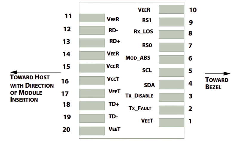
Figure 1. MSA compliant connector.
|
PIN |
Symbol |
Description |
Logic |
Note |
|
1 |
VeeT |
Transmitter Ground |
|
|
|
2 |
TX_Fault |
N/A |
LV-TTL-O |
|
|
3 |
TX_DIS |
Transmitter Disable |
LV-TTL-I |
|
|
4 |
SDA |
Tow Wire Serial Data 5 LV |
LV-TTL-I/O |
|
|
5 |
SCL |
Tow Wire Serial Clock |
LV-TTL-I |
|
|
6 |
MOD_DEF0 |
Module present, connect to VeeT |
|
|
|
7 |
RS0 |
N/A |
LV-TTL-I |
|
|
8 |
LOS |
LOS of Signal |
LV-TTL-O |
|
|
9 |
RS1 |
N/A |
LV-TTL-I |
|
|
10 |
VeeR |
Receiver Ground |
|
|
|
11 |
VeeR |
Receiver Ground |
|
|
|
12 |
RD- |
Receiver Data Inverted |
CML-O |
|
|
13 |
RD+ |
Receiver Data Non-Inverted |
CML-O |
|
|
14 |
VeeR |
Receiver Ground |
|
|
|
15 |
VccR |
Receiver Supply 3.3V |
|
|
|
16 |
VccT |
Transmitter Supply 3.3V |
|
|
|
17 |
VeeT |
Transmitter Ground |
|
|
|
18 |
TD+ |
Transmitter Data Non-Inverted |
CML-I |
|
|
19 |
TD- |
Transmitter Data Inverted |
CML-I |
|
|
20 |
VeeT |
Transmitter Ground |
|
|
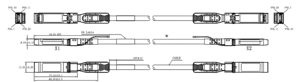
Mechanical Dimension
Order Information
Table 1- order information
|
Part No. |
Data Rate |
Fiber Type |
Distance |
Temp |
DDM |
|
HC-10G-D1 |
10.3125Gbps |
Copper |
0.5-7M |
0-70℃ |
N |
Если вам нужна дополнительная информация, пожалуйста, свяжитесь с нами.
