

单击打开
射频激光器
Description
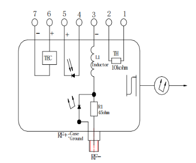
HC-9015 series module is 1550nm Non-WDM or WDM MQW DFB laser, The 9015 series modules are intended for use in the transmission of broadband analog signals or digital signals. The lasers built in optical isolator, TEC, thermistor, laser, and monitor photodiode are hermetically sealed in a butterfly package.
Features
1550nm, or WDM
MQW DFB Laser diode module
Directly Modulated DFB Lasers
High-frequency response up to 18GHz
SMA or K Connector RF port
Application
Telecom/datacom
RF over fiber
Analog RF links transmission
Test and measurement
RF Delay line
|
Pin Assignments |
|
|
Pin |
Function |
|
1 |
Thermistor |
|
2 |
Thermistor |
|
3 |
DC Bias Laser cathode (-) |
|
4 |
MPD Anode |
|
5 |
MPD Cathode |
|
6 |
TEC (+) |
|
7 |
TEC (-) |
|
RF connector |
Laser cathode RF |
|
Case ground |
Laser Anode |
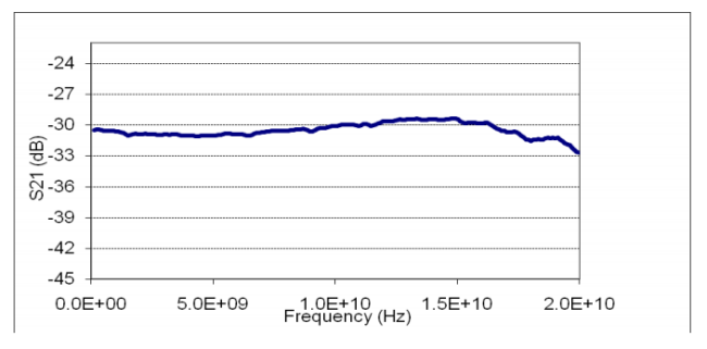
S21 Data
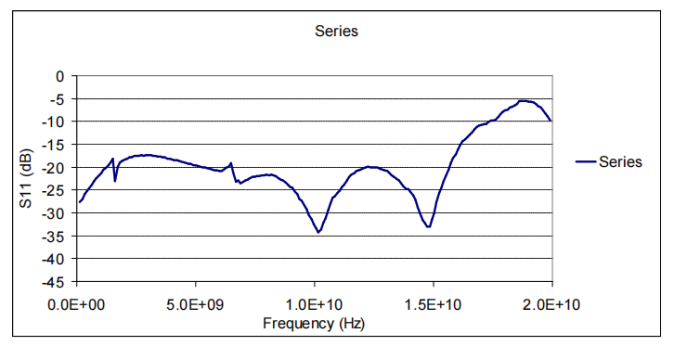
S11 data
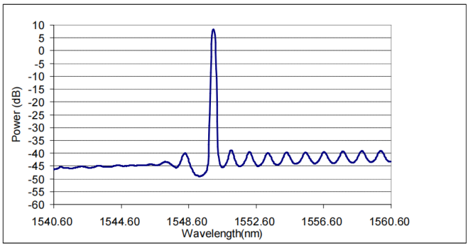
Typical Spectrum data
Fiber Characteristic
Type: single mode SMF28E, Hytrel 900um diameter
Fiber length: 900mm minimum
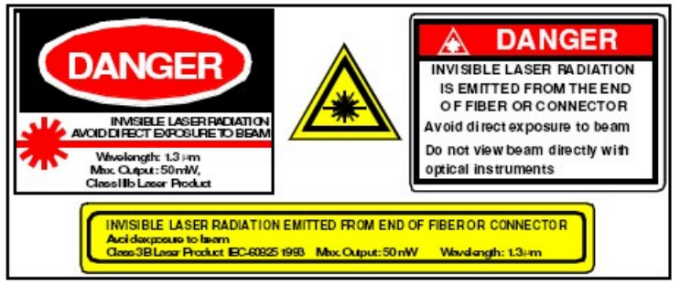
Laser Safety
FDA/CDRH Class IIIb laser product. All versions are Class IIIb laser products per CDHR 1040 Laser Safety Requirements. All versions are class 3B laser products per IEC_ 60825-1:1993. The device has been classified with the FDA under accession number 220191.
This product complies with 21 CFR 1040.10 and 1040.11.
PM fiber pigtail
Wavelength = 1550nm
Maximum power = 50 mW
Because of size constraints, laser safety labeling (including an FDA class IIIb label) is not affixed to the module but attached to the outside of the shipping carton.
Product is not shipped with power supply.
Caution: Use of controls, adjustments and procedures other than those specified herein may result in hazardous laser radiation exposure.
Ordering information
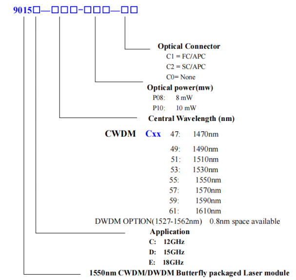
9015E-P10-C1 means 18GHZ 1550nm Non-WDM laser module,
9015E-C49-P10-C1 means 18GHZ 1490nm CWDM laser module,
9015E-W34-P10-C1 means 18GHZ 1550.12nm DWDM laser module,
Performance Absolute Maximum Ratings
|
Parameter |
Symbol |
Rating |
Units |
Test condition |
|
Laser reverse voltage |
Vrl |
2.0 |
V |
- |
|
Photodiode reverse voltage |
Vrd |
20 |
V |
- |
|
Storage Temperature |
Ts |
-40~+85 |
℃ |
- |
|
Operating Case Temperature |
TO |
-20~+65 |
℃ |
- |
|
TE Cooler Current |
Ic |
1.7 |
A |
-- |
|
RF Input Max. power |
Pin |
20 |
dBm |
-- |
Electrical/Optical Characteristics (Tc=25℃)
|
Symbol |
Parameter |
Test conditions |
Min |
Typ |
Max |
Unit |
|
Ith |
Threshold Current |
CW |
- |
- |
25 |
mA |
|
Iop |
Operating Current |
CW |
- |
- |
100 |
mA |
|
Zin |
Input impedance |
IF=Iop |
- |
50 |
- |
Ω |
|
RT |
Thermistor Resistance |
@+25℃ |
9.5 |
10 |
10.5 |
kΩ |
|
|
Thermistor Temp. Coeff. |
@+25℃ |
- |
-4.4 |
- |
%/℃ |
|
lc |
Center Wavelength |
NON-WDM |
1530 |
|
1560 |
nm |
|
@+25℃ |
CWDM available |
lc-3 |
lc |
lc+3 |
nm |
|
|
100GHz spacing |
DWDM available |
lc-0.4 |
lc |
lc+0.4 |
nm |
|
|
PF |
Optical Output Power from fiber |
CW, IF=Iop See Options |
|
10 |
|
mW |
|
SMSR |
Side Mode Suppression Ratio |
CW, IF=Iop |
34 |
- |
- |
dB |
|
RIN |
Relative intensity Noise |
100MHz-3GHz |
|
-150 |
|
dB/Hz |
|
Im |
Monitor Current |
- |
10 |
- |
200 |
uA/mW |
|
|
Optical Isolation |
- |
30 |
|
|
dB |
|
NF |
Noise figure |
IF=Iop@18GHz |
- |
|
57 |
dB |
|
S21 |
-3dB RF Bandwidth |
Options C Options D Options E |
12 15 18 |
- - - |
-
|
GHz |
|
S11 |
Return loss |
DC-10GHZ 10-18GHZ |
8.0 5.0 |
|
|
dB |
Notes
RF amplitude flatness tested Peak to Peak, optical path requires return loss better than 40dB.
NF test under No RF signal input.
